The difference between a $5/kg industrial silica filler and a $50/kg electronic-grade fused silica filler is not the raw material. It is the production process. Both start with high-purity quartz. What separates them is the precision of every step between the quarry and the final product bag. They’re the melting conditions, the grinding technology, the classification precision, and the contamination controls applied at each stage.
Electronic-grade fused silica is the primary filler in semiconductor epoxy molding compounds and PCB laminates. One oversized particle can cause wire sweep during molding or signal loss at 28 GHz. The production process must prevent both defects consistently, batch after batch. This article covers the seven-stage production chain: raw material selection, melting, grinding, classification, surface treatment, and contamination control. Each stage has specific quality parameters that determine whether the final product meets the specifications required by semiconductor packaging engineers.
What Makes Fused Silica ‘Electronic Grade’ — The Specification Threshold
Fused silica is amorphous silicon dioxide produced by melting high-purity crystalline quartz above 1,720°C. Melting transforms crystalline quartz into a disordered glassy network—creating amorphous fused silica. This amorphous structure gives fused silica an extremely low CTE (0.5 ppm/°C vs. 12-17 ppm/°C for epoxy resin). Low CTE makes it valuable for semiconductor packaging by matching silicon’s expansion rate. It reduces thermomechanical stress during solder reflow and thermal cycling. But ‘fused silica’ covers a wide range of products. A combination of chemical purity, particle size specification, and amorphous content defines electronic grade—requirements most industrial fused silica does not meet.
| مواصفة | Standard EMC Grade | Fine-Pitch / BGA Grade | Ultra-Fine / WLP Grade |
| D50 (median size) | 5–10 μm | 3–6 μm | 1–3 μm |
| D97 / D98 maximum | <25 μm | <15 μm | <8 μm |
| Dmax (absolute maximum) | <45 μm | <25 μm | <12 μm |
| SiO2 purity (minimum) | 99.9% | 99.95% | 99.97% |
| Amorphous content | ≥99% | ≥99.5% | ≥99.9% |
| Fe2O3 maximum | <30 ppm | <10 ppm | <5 ppm |
| U + Th (radioactivity) | <1 ppb each | <0.5 ppb each | <0.2 ppb each |
Specifications vary by customer and application. The above represents typical industry ranges. Verify against your cell manufacturer or packaging house specification before production.
Two specifications in this table deserve explanation. U and Th radioactivity limits prevent alpha-particle-induced soft errors in DRAM and logic devices. These single-event upsets cause invisible reliability failures in the field. Radioactivity screening of fused silica filler is now standard for memory packaging. Health and performance reasons require amorphous content ≥99%. Residual crystalline quartz is a carcinogen by inhalation. Its dielectric properties also differ from amorphous SiO₂, affecting high-frequency signal integrity.
Stage 1 — Raw Material Selection
The quality ceiling of the final product is set here. No downstream processing step can raise the purity above what the raw material provides — it can only preserve it or degrade it. Most electronic-grade fused silica producers work with high-purity vein quartz: SiO₂ typically 99.5–99.9%, sourced from deposits where the crystalline structure is large enough to allow physical separation of impurity mineral inclusions.
Natural Quartz vs. Synthetic Precursors
Natural vein quartz remains the primary commercial feedstock for EMC-grade fused silica despite its variability. Synthetic SiO₂ precursors offer higher purity but cost 5-10 times more than natural quartz. At 70-85% filler loading, synthetic feedstock becomes uneconomical for volume semiconductor packaging. Critical raw material parameters include SiO₂ assay, trace metal profile, and moisture content. Impurity distribution in the feed is verified by XRF and ICP-MS analysis. Fluid inclusions or mineral veins concentrate alkali metals and iron in quartz deposits. These contaminants appear in the melt and cannot be removed later.
Radioactivity Screening
Low-background alpha particle counting screens alpha emission from uranium and thorium decay chains, typically measuring counts per hour per unit area. This test is not fast — a 24-hour counting period is standard for low-level screening. Supply chains serving advanced logic and DRAM packaging quarantine raw material lots until radioactivity screening completes.
A single high-U lot that passes chemical QC but fails the radioactivity screen disrupts the supply chain significantly if melting begins before detection.
Stage 2 — Melting and Vitrification
Converting crystalline quartz to amorphous fused silica requires sustained temperatures above 1,720°C — well above the quartz melting point of approximately 1,650°C. The difference matters: material heated only to 1,650°C undergoes partial phase transformation and retains residual crystalline content that will show up in XRD analysis of the final product.
Electric Arc Fusion vs. Hydrogen-Oxygen Flame Fusion
Two industrial melting routes are in commercial use, and they produce different products.
Electric arc fusion uses graphite or tungsten electrodes to generate the required temperatures. It handles large production volumes (tonnes per batch) and is the dominant technology for standard-grade and most industrial-grade fused silica. The contamination risk is electrode wear: graphite electrodes contribute carbon to the melt; metal electrodes contribute trace metals. Both are manageable with process control, but they impose a ceiling on achievable purity that makes electric arc fusion less suitable for the highest-grade electronic applications.
Hydrogen-oxygen flame fusion burns H₂ and O₂ to generate a clean, high-temperature flame (above 2,000°C at the reaction zone). There are no electrodes, no metal parts in contact with the melt, and the only process gases are hydrogen and oxygen. This route produces higher-purity fused silica at lower throughput and higher cost per kilogram. It is the preferred method for ultra-fine and ultra-high-purity grades where the electrode contamination of arc fusion would exceed the impurity specification.
One trade-off unique to flame fusion: the combustion of hydrogen produces water vapour, which can introduce hydroxyl (–OH) groups into the glass network. Residual –OH increases the dielectric loss tangent at microwave frequencies — a concern for PCB laminate applications at 5G bands. Managing moisture in the process atmosphere (controlling the H₂/O₂ ratio and the furnace atmosphere) keeps –OH below the threshold that affects electrical performance.
Quality Gate After Melting
•XRD analysis: to quantify amorphous content — Rietveld refinement should show <0.5% crystalline phases for electronic-grade material
•ICP-MS re-analysis: to verify no contamination was introduced during melting — compare pre- and post-melt trace metal profiles
•Visual inspection: check for unmelted zones, inclusions, and large bubbles in the ingot or lump before crushing
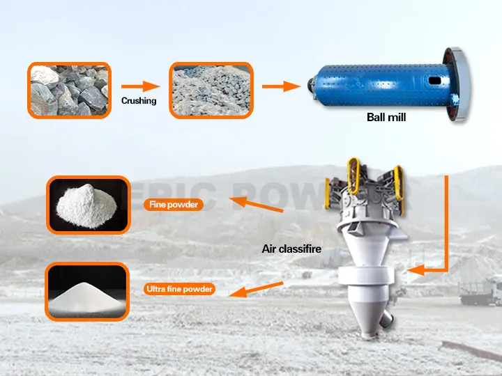
Stage 3 — Primary Size Reduction: Crushing and Pre-Grinding
Fused silica exits the melting stage as ingots, lumps, or slabs — feed material that needs to be reduced to a processable size before fine grinding. This stage is about efficient size reduction without introducing the metallic contamination that would undermine everything achieved in the melting stage.
Jaw crushing reduces ingots from 50-200 mm down to <10 mm. The contamination risk is jaw plate wear: standard manganese steel jaw plates liberate iron at levels that are unacceptable for electronic-grade material. Producers use high-alumina ceramic jaw inserts or tungsten carbide composite jaw plates for primary crushing of electronic-grade fused silica. Both add cost but prevent iron introduction at a stage where the mass flow rate is high enough to make contamination correction downstream impractical.
Pre-grinding to 100-200 mesh (75-150 μm) uses a roller mill or ball mill with ceramic lining — alumina or zirconia depending on the impurity specification. The target at this stage is a consistent feed PSD for the fine grinding step: 100% passing 150 μm, with D50 typically in the 30-60 μm range. Over-grinding at this stage wastes energy without benefit; under-grinding creates an inconsistent and coarser feed for the fine grinding step that shifts the operating point of the classifier circuit.
Stage 4 — Fine Grinding to Target Particle Size
The application’s D50 specification—ranging from 1 μm to 15 μm—now determines how finely operators must grind the pre-ground fused silica feed. Two technologies exist for this reduction step. The target fineness and contamination budget primarily drive the technology choice.
Ball Mill with Air Classifier (Standard and Medium Grades)
For standard EMC grades with D50 5-15 μm and D97 below 25-45 μm, a ceramic-lined ball mill in closed circuit with a dynamic air classifier is the most energy-efficient choice. The mill reduces particle size; the classifier sorts the output, returning oversized particles to the mill and sending on-spec particles to the product collection system. This closed-circuit design prevents over-grinding: particles exit the circuit as soon as they meet the size specification, rather than continuing to be ground finer than needed.
Contamination management: the ball and liner material must match the impurity tolerance of the product. For most standard EMC applications, alumina (Al₂O₃) balls in an alumina-lined mill is the correct pairing — the Al contamination introduced by liner wear is acceptable in SiO₂-based EMC formulations. For applications where even Al contamination is specified at below 50 ppm, zirconia balls in a zirconia-lined mill eliminates the Al pathway at higher equipment cost.
Jet Milling for Fine and Ultra-Fine Grades
For fine-pitch and WLP grades requiring D50 below 5 μm and Dmax below 15 μm, fluidised bed jet milling is the standard process. The key advantage is the grinding mechanism: particles fracture by colliding with each other at high velocity, driven by compressed gas jets. There are no grinding surfaces in contact with the product — the only solid surfaces are the chamber walls and the classifier wheel, both of which can be ceramic-lined. Metal contamination from the grinding step approaches zero.
The compressed gas must be dry and oil-free. Moisture in the grinding gas at fine particle sizes causes particle agglomeration at the classifier, which broadens the PSD and raises D97 unpredictably. An inline dew point monitor at the gas inlet is standard practice for production of fine-grade fused silica.
The energy cost of jet milling is 3-4 times higher per tonne than ball milling for the same target D50. For fine-grade fused silica at $40-80/kg, the energy premium is easily justified. The cross-over point — where jet milling becomes the more economical total-cost choice relative to ball milling plus extensive contamination controls — is typically around D50 4-5 μm.
Angular vs. Spherical: The Morphology Question
Both ball milling and jet milling produce angular particles. Fracture mechanics guarantee this — grinding breaks material along stress concentration planes, producing irregular fragments regardless of the technology used. Angular fused silica is suitable for standard EMC at loading up to approximately 80% by weight.
Advanced packages requiring the lowest CTE demand loading above 80%. Angular particles generate excessive viscosity in the compound at these loading levels, impeding transfer moulding flow. Manufacturers produce spherical fused silica by passing fine angular powder through a hydrogen-oxygen flame (flame spheroidisation). The spheroidisation process does not change particle chemistry or amorphous content; it converts the particle shape through surface tension effects in the molten state. The cost premium is significant (typically 2-3× per kilogram vs. angular product of the same PSD) and is justified only for applications where the loading target cannot be achieved with angular filler.
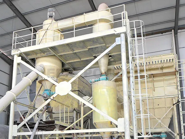
Stage 5 — Classification to Final Particle Size Specification
This is the stage that sets the final PSD — and for electronic-grade applications, it is the most technically demanding step in the production chain. Grinding establishes the approximate D50. Classification defines D97, Dmax, and span with the precision that semiconductor packaging specifications require.
Why Classification Cannot Be Skipped
Grinding produces a broad, continuous distribution of particle sizes. A ball mill or jet mill operating at a given energy input will produce material ranging from sub-micron particles up to particles 5-10 times the D50. The D97 of unclassified mill output is typically 3-5 times the D50 — meaning that for a D50 of 5 μm, Dmax values of 30-50 μm are common without classification. For a wire bond pitch of 0.4 mm, particles above 25 μm are killer particles. Classification is not optional.
Single-Stage Air Classification (Standard Grades)
A dynamic air classifier separates particles by the balance of centrifugal force and aerodynamic drag at the classifier wheel face. Wheel rotation speed controls the cut point: higher speed rejects larger particles back to the mill, finer particles pass through to product. For standard EMC grades where D97 must be below 25 μm, a single-stage classifier is adequate — the separation sharpness achievable with a well-configured single rotor is sufficient to hit this target consistently.
Multi-Stage Classification for Fine Grades
For fine-pitch and WLP grades where D97 must be below 10-12 μm, a single classifier stage does not provide sufficient separation sharpness. The transition zone between particles that are classified as fine and particles that are rejected as coarse is too broad — some particles above the target D97 slip through to product. A two-stage classification circuit addresses this: the first classifier sets the D50; the second operates as a sharp upper-cut classifier, specifically targeting the coarse tail and ensuring Dmax stays below the specification limit. The two-stage approach increases equipment cost and reduces throughput per unit of installed classifier capacity, but it is the only reliable way to hold D97 below 10 μm with the consistency that electronic-grade supply chains require.
Horizontal classifier geometry has a specific advantage for fine grades. In a vertical-axis classifier, gravitational settling of larger particles partially offsets the centrifugal rejection force — at cut points below 5 μm, this creates an asymmetric separation that broadens the distribution on the coarse side. Horizontal-axis classifiers eliminate this effect by orienting the classification zone perpendicular to gravity, producing sharper cuts at fine particle sizes.
In-Line PSD Monitoring
For electronic-grade production, batch-end sampling is insufficient QC. A 4-hour production run that starts with D97 within specification but drifts above specification in the last 90 minutes produces a mixed batch — some of which is on-spec, some of which is not. Separating them after the fact is impractical. An in-line laser diffraction sensor at the classifier product outlet, logging D10, D50, D90, D97 every 30-60 seconds, is the standard solution. Classifier wheel speed is slaved to the D97 reading via a feedback controller: when D97 trends upward, wheel speed increases to tighten the cut. This keeps the product within specification continuously rather than checking after the fact.
| Minimum Certificate of Analysis Parameters for Electronic-Grade Fused Silica PSD parameters: D10, D50, D90, D97, and Dmax — all five are required. D50 alone is insufficient for EMC qualification. Chemistry: SiO2 purity (XRF), Fe2O3, Al2O3, Na2O, K2O, TiO2 (ICP-MS) — each with certified maximum values Amorphous content: Quantitative XRD (Rietveld method) — certified as percentage amorphous Specific surface area: BET measurement — relevant for binder demand and viscosity prediction in the EMC formulation Radioactivity: U and Th by alpha counting or ICP-MS — required for logic and memory packaging supply chains Morphology: Spherical or angular, confirmed by SEM — relevant for loading capacity specification |
Stage 6 — Surface Treatment
Not every electronic-grade fused silica application requires surface treatment, but high-loading EMC formulations generally do. The issue is surface chemistry. Native fused silica has a hydrophilic surface covered with silanol (Si–OH) groups that form hydrogen bonds with water. Epoxy resin matrices are hydrophobic. At low filler loading, the resin can wet the filler surface adequately despite this mismatch. At 80-85% filler loading by weight, the viscosity consequence of inadequate surface wetting is severe enough to prevent transfer moulding.
Silane Coupling Agents
Silane coupling agents solve this by reacting with the surface silanol groups and replacing them with organofunctional groups that are compatible with the epoxy resin chemistry. The reaction attaches the silane molecule to the silica surface through a Si–O–Si bond; the organofunctional end group (epoxy, amino, or methacrylate depending on the resin system) then co-reacts with the matrix resin during curing.
Epoxy-functional silane (glycidoxypropyltrimethoxysilane) is the most common coupling agent for standard bisphenol-A epoxy EMC systems. Manufacturers use aminosilane where resin chemistry favours amine co-reactants. Thermogravimetric analysis (TGA) verifies treatment coverage by measuring mass loss from the organic coating layer. Contact angle measurement confirms the hydrophilic-to-hydrophobic conversion.
Producers prefer dry treatment (gas-phase silane in fluidised bed or impact reactor) for fine-grade fused silica below D50 5 μm. Wet treatment at fine particle sizes causes agglomeration—the liquid coating agent bridges between adjacent particles before fully distributing. Agglomerated product requires re-classification, adding cost and reducing yield.
Stage 7 — Contamination Control Across the Full Chain
The quality of the final product reflects the cumulative effectiveness of contamination controls at every stage. Each of the following practices addresses a specific contamination pathway that has caused batch failures in electronic-grade fused silica production.
الفصل المغناطيسي
High-gradient magnetic separators (10,000-15,000 Gauss) are positioned after each size reduction stage. Magnetic separators remove ferromagnetic wear particles from upstream equipment before they reach the next stage. These particles include jaw plate fragments, mill ball chips, and liner spall. At fine sizes, magnetic particles are dangerous—they pass through classifiers and distribute uniformly. A 2 μm iron particle in D50 5 μm silica evades laser diffraction detection. It would be captured by HGMS or detected by ICP-MS in final testing.
Cleanroom-Class Packaging
Once the product passes final classification, any recontamination must be prevented. Packaging in a positive-pressure clean area with HEPA filtration prevents atmospheric particulate from entering open product containers. All packaging materials in contact with the product must be qualified for trace metal contribution — some polyethylene bag grades contain metal-based heat stabilisers that can leach into ultra-high-purity fused silica.
Final QC Battery
| Test | Instrument | What It Verifies |
| Particle size distribution | Laser diffraction (in-line + final lot) | D10, D50, D90, D97, Dmax — all five must be within specification |
| النقاء الكيميائي | XRF (major elements) | SiO2 content and major impurity oxides |
| Trace metals | ICP-MS | Fe, Al, Na, K, Ti, and other specified elements at ppm to sub-ppm level |
| Amorphous content | XRD (Rietveld method) | Crystalline quartz content — must be below specification limit |
| Specific surface area | BET (nitrogen adsorption) | Surface area in m2/g — relevant to binder demand and silane coverage |
| Radioactivity | Alpha particle counting or ICP-MS for U/Th | U and Th — required for advanced logic and memory packaging |
| Surface treatment verification | TGA + contact angle | Silane coverage uniformity and hydrophobic conversion confirmation |
| Need Grinding or Classification Equipment for Electronic-Grade Fused Silica? EPIC Powder Machinery supplies jet mills, ball mills with ceramic liners, and multi-stage air classifiers configured specifically for electronic-grade fused silica production. All product-contact surfaces are available in alumina or zirconia ceramic. We offer free classification trials on your feed material before equipment commitment.Send us your feed PSD and your target D50, D97, and Dmax specification and we will confirm what is achievable and run a trial grind. Request a Free Classification Trial: www.quartz-grinding.com/contact Explore Our Fused Silica Processing Equipment: www.quartz-grinding.com |
الأسئلة الشائعة
What is the difference between fused silica and fumed silica — can they be used interchangeably as EMC fillers?
Completely different processes produce these materials at completely different particle size scales. Manufacturers melt fused silica above 1,720°C, then grind it to D50 1-15 μm for EMC filler. Fused silica structurally reduces composite CTE through high loading at 70-85% by weight.
Flame combustion produces fumed silica, yielding 10-20 nm particles with 50-400 m²/g surface area. Its role is rheological—it controls flow and thixotropy at 0.1-1% addition levels. Fumed silica as structural filler would require excessive binder to wet its surface area. Fused silica as rheology modifier is ineffective due to low surface area per unit mass.
What is the production cost penalty for going from D97 25 μm (standard EMC) to D97 8 μm (fine-pitch grade)?
Three cost factors compound as the specification gets finer. Jet milling to D50 3 μm costs 3-4x more in compressed gas than grinding to D50 8 μm. Achieving D97 below 10 μm requires multi-stage classification at 40-60% lower throughput. Fine grades have higher recycle rates, increasing energy cost per tonne of on-spec output. Ultra-fine WLP-grade (D50 1-3 μm) costs 3-5x more than standard EMC-grade from the same raw material.
Can EPIC Powder Machinery’s equipment handle the full production chain for electronic-grade fused silica?
آلات مسحوق EPIC supplies equipment for stages 4 and 5 of the production chain — fine grinding and classification. For fine grinding: fluidised bed jet mills with ceramic contact surfaces for fine and ultra-fine grades (D50 below 5 μm), and ceramic-lined ball mills in closed circuit with air classifiers for standard and medium grades (D50 5-15 μm). For classification: single-stage dynamic air classifiers for standard EMC grades (D97 below 25 μm) and multi-stage classification systems with horizontal classifier geometry for fine-pitch and WLP grades (D97 below 10-12 μm). All systems are available with in-line laser diffraction monitoring integrated with the classifier control system. We offer free classification trials on customer-supplied fused silica feed at our test facility, producing full PSD, surface area, and contamination data before any equipment commitment.
مسحوق ملحمي
مسحوق ملحمي, 20+ years of experience in the ultrafine powder industry. Actively promote the future development of ultra-fine powder, focusing on crushing, grinding, classifying and modification process of ultra-fine powder. Contact us for a free consultation and customized solutions! Our expert team is dedicated to providing high-quality products and services to maximize the value of your powder processing. Epic Powder—Your Trusted Powder Processing Expert!

شكرًا لقراءتكم. آمل أن يكون مقالي مفيدًا. يُرجى ترك تعليق أدناه. يمكنكم أيضًا التواصل مع ممثل خدمة عملاء EPIC Powder عبر الإنترنت. زيلدا "لأي استفسارات أخرى."
— إميلي تشين, مهندس